The Unsprung Secrets
puzzle seeks
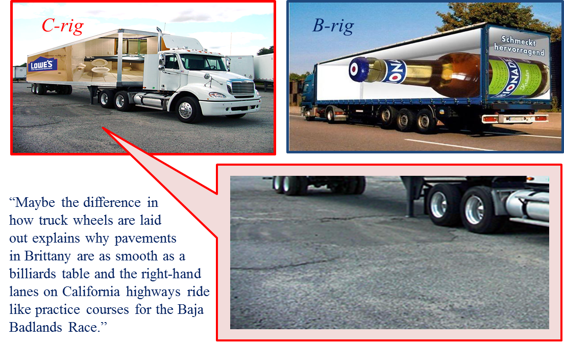
an explanation for why C-rigs
damage roadways in California more
than B-rigs
in Brittany. The secrets must be in
their designs.
In either case a truck-wheel deflected by the
roadway requires a momentary change in its
tangential -- and therefore its angular
-- velocity. Such changes are resisted
by inertia,
and not all truck-wheels are the same in that
regard. Three categories come to mind...
SteeringWheel SW..............................
same configuration for both rigs Drive WheelDW................ duals
onB-rigs
and tandem-duals on C-rigs Trailer
WheelTW...tandem-duals on C-rigs
and tridem-singles onB-rigs
So far we have
treated all wheels as independent of one
another with respect to their angular
rotations. That's appropriate for both SWs
and TWs, which are simply 'coasting'
on the roadway surface. However, as
essential features of the tractor's drive
train, DWs
deliver tractive effort to the roadway via
shear forces in their respective contact
patches.
Inasmuch as our
suspicion has to do with where the
rubber meets to road, we must note
the fact that the C-rig
tractor has twice as many drive-wheel
contact patches as the B-rig, which means
less damage not more, ceteris
parabus.
Drive-Train
A Review of the Hardware
For a pleasant review of this subject and
others, solvers are invited to enjoy this
animated
video of a drive-train
design which is typical of the tractor on a B-rig...
Non-drive
wheels, SWs
and TWs, go
along spinning at whatever
tangential speed complies with the local
profile of the roadway. Each SW
or TW can be individually
accelerated or decelerated by the roadway
pavement. Drive-wheels DWs
are a different matter entirely. For
producing tractive
effortDWs must
be 'torqued' by the truck's drive-train,
which
means applying
twisting forces through their
respective axles.
Oh sure, to
accommodate turns and roadway
curves, a drive-axle must
be split to allow an
outside DW to rotate
more rapidly than the corresponding
inside DW. That does not,
however,give
DWs complete 'independence'
from one another. That
will be addressed as a
separate topic (Differential
Differences).
For now,
let's postulate straight
roadway and regard
drive-axles
as
not split.
Drive-Train:
B-rig
vs
C-rig
Real Difference in Design
As is
obvious to anyone who sees typical camions
plying the routes
in Brittany, a B-rig
tractor has only one
drive-axle. Meanwhile, on the
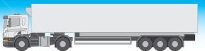
roadways in California the C-rig,
which is best known by the sobriquet
"18-wheeler," is seen to have two
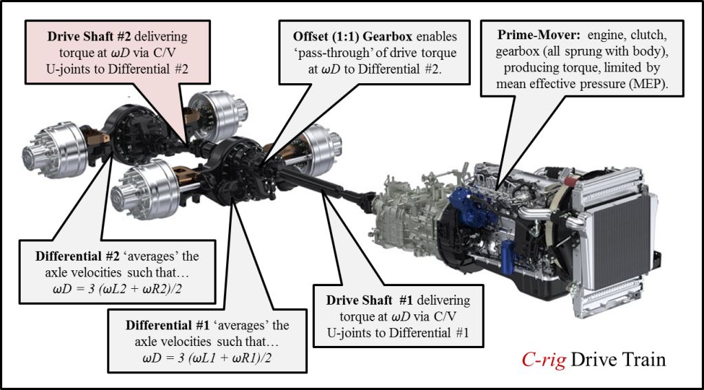
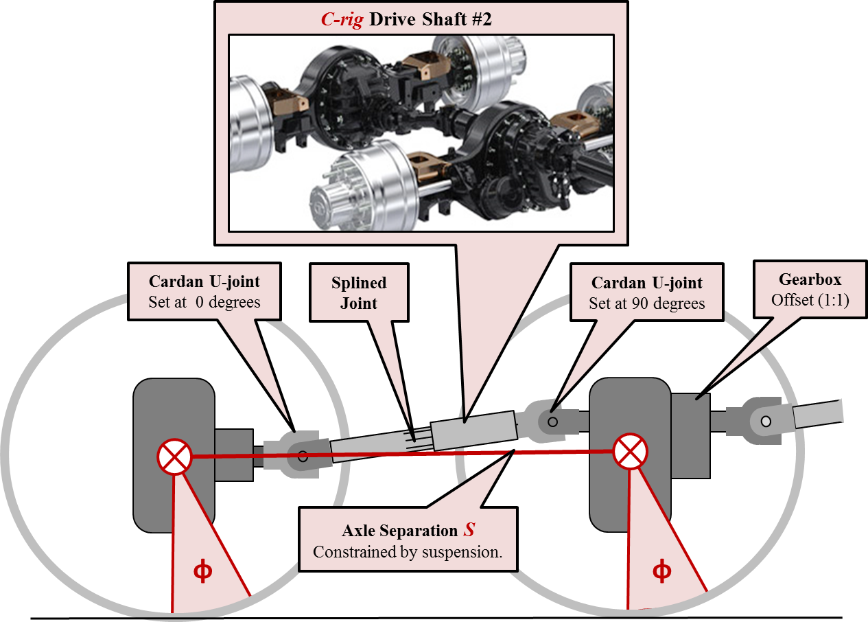
drive-axles. Here is a
cutaway of the drive-train on a C-rig
tractor...
In the video
we saw how a single drive
shaft on a B-rig delivers
tractive effort as torque from the engine to
its single drive-axle via its single differential.
As shown in the cutaway above, the C-rig tractor
has two drive-axles, two differentials, and a
second drive shaft in between. That
mechanical configuration assures that both
drive-axles are provided with equal torques
produced by the engine. That seems like
a good idea (for large values of "seems").
On a C-rig
tractor traveling at a constant speed vX
along a perfectly flat roadway, all four
dual-wheels will have the same tangential
velocity vX and angular velocity
both left and right:
ωL1 = ωR1= ωL2= ωR2
= vX / rW. With a 3:1
ratio in the differentials, both drive
shafts must have the same angular velocity ωD, which is three times
faster than the DWs. At a
highway speed of 60 mph (vX = 88
fps), 42-inch DWs (3.5
ft in diameter) will be
turning at 480 rpm and the drive shaft
coming out of the gearbox spins at 1,440 rpm
such that ωD = 150 radians/second.
Same for the 'offset gearbox' in the
cutaway above. The more common
expression is 'transfer case', which is a
necessary feature in four-wheel
drive trucks and passenger vehicles
wherein gearing or a drive-belt must be
used to facilitate other than 1:1
ratio for accommodating
different-size wheels front and
rear. To address that requirement, a
'center differential'
is often integrated
into the transfer case.
Meanwhile, vehicles with all-wheel
drive so popular in
California can
seldom be seen in Brittany, which may
explain the lack of 'washboarding'
observed by the author even on unpaved
roads.
Most significant to the Unsprung Secrets
solution is the fact that the two
drive-axles on a C-rig
tractor are not independent. The drive-train coerces the
angular velocities of all DWs
to be the same regardless of any local
disparities in the roadway. By
definition, if angular velocities
are the same and the wheel radii are
the same, then during a given time
interval, the circumferential
displacements of all DWs
must be identical to one
another.
Identicalcircumferential
displacements of C-rigDWs can result in scuffing
action at
contact patches located on
segments of roadway that
do not have identical
profiles.
C-rig-Specific
Phenomenon
Discovery
of Shear Pulse
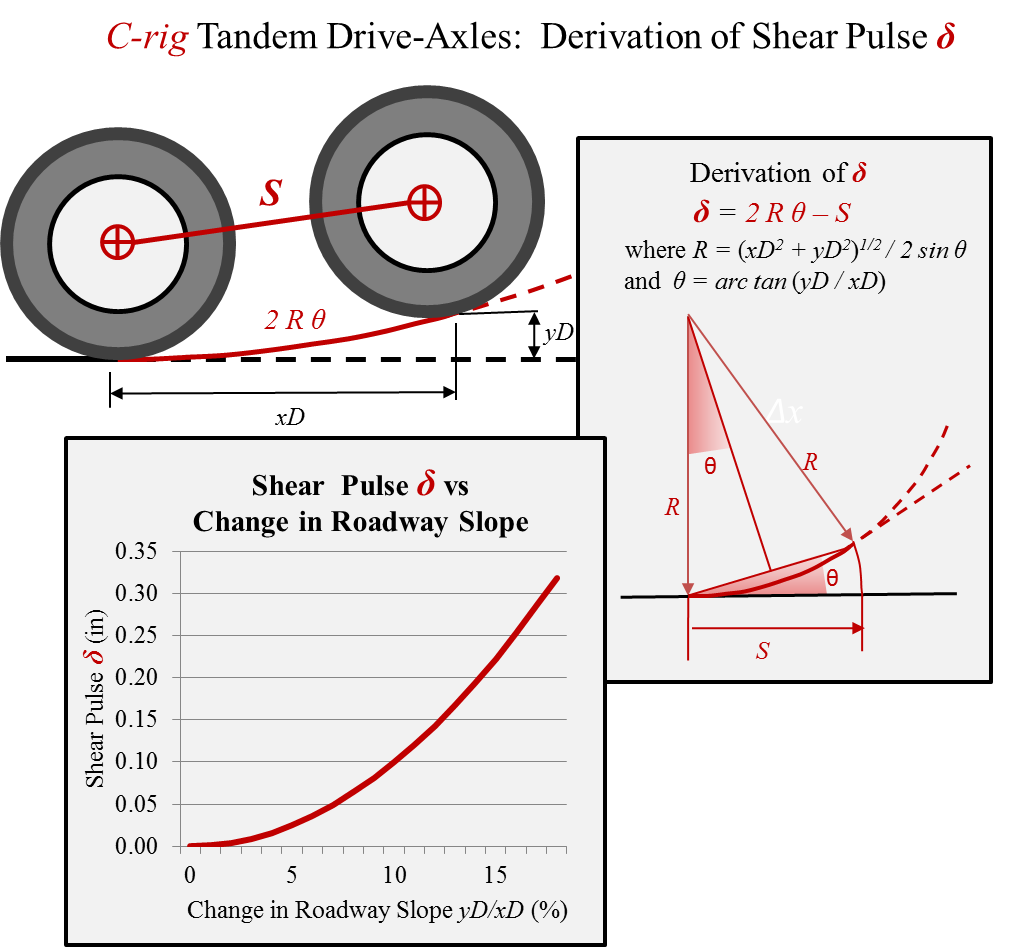
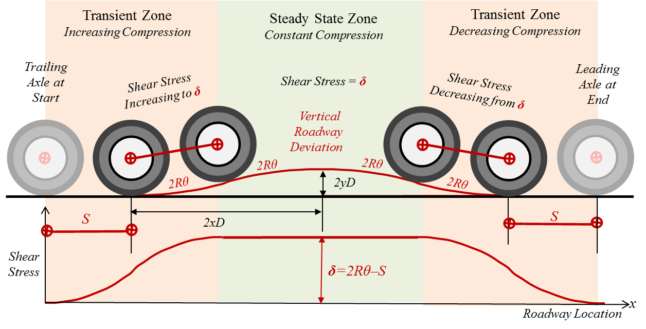
The sketch
below depicts wheels on the
tandem drive-axles of a C-rig
tractor as they sequentially
encounter a deflection yD
in the roadway. The
vertical profile of the
roadway is assumed to be the
the gentle arc of a
circle. The distance
between the axles S
is held constant by the
suspension system (typicallyS
= 5 ft). Before coming
to the arc, yD = 0 which
assures that xD = S
and that the trailing drive-axle
reaches any point on the roadway at a
distance exactly Sbehind the leading
drive-axle.
For yD ≠
0, the projected location
of the leading
drive-axle will be forced
by the roadway pavement to
travel a longer distance
than the trailing
drive-axle during the same
interval of time tD.
While
the trailing drive-axle
is traveling xD = S,
the leading drive-axle
is traveling 2Rθ
as shown in the sketch.
The theoreticaldifference
in circumferential distance
traveled by the two drive
axles is given byδ
= 2Rθ -
S, where δ ≡
shear
pulse.
The
expression shear pulse
is an in situ coinage for Unsprung Secrets.
The graph above indicates that for a
change in roadway slope of about 15%,
the shear pulseapproaches
a quarter of
an
inch
of
scuffing
action
on the
pavement
surface.
For
undamaged
roadway,
however, one
would expect a
much smaller shear
pulse,
such that the
tire would
not actually
scrub the
pavement
surface but
only deform
elastically.
Meanwhile...
In realityδ =
0.
Always. In
order for δ ≠ 0,
the
two drive-axles
would have to
rotate different
amounts during
the same time
interval, which
is mechanically
forbidden
by Drive Shaft
#2
Drive
Shaft #2
Mechanical
Coercion in the C-rig
The sketch below shows details about
Drive Shaft #2, giving emphasis to the
reality that instantaneous angular
displacementφ is
identical for the
tandem drive-axles on a C-rig.
The tandem drive-axles are unsprung,
thus vertically independent of one
another. Best keep in mind, however,
Drive Shaft #2 has absolute angular
authority over the two
drive-axles. Think
steel-on-steel. The drive-train
design in a C-rig
tractor assures equivalence in angular
displacementφ
for all values of
φ.
That absolute
angular authority
is maintained at any speed of the truck
vX.
By the way, the shear pulse
phenomenon is independent of tractive
effort. Any damage from δ ≠ 0
can occur even if the C-rig is
coasting with its transmission in neutral.
Differential
Differences
Unfair bullying'
is sanctioned
by tandem differentials
Sophisticated solvers know
that the so-called differential
on a roadway vehicle
enforces mechanical
averaging
of angular rotations between its
left DW and its right DW, which enables the vehicle
to negotiating turns and
roadway curves without scuffing
action.
Roadway
geometry
balances the
operation, such
that the
outside DW rotates through
an angle φ +∆φ while
the inside DWrotates
through
an angle φ - ∆φ.
The average
'computed' by the
differential will
be [(φ + ∆φ) +
(φ - ∆φ)]/2
=φ.
Vertical roadway deflections will not
always be so polite.
Let us suppose that a B-rig
with its single drive-axle encounters a
vertical deflection on the left-hand
side of the roadway, which causes the
left DW to rotate through an
angleφ +∆φ while
the right DW continues to rotate through
angle φ.
The
average
'computed'
by the differential
would be given by [(φ + ∆φ) +
φ]/2
=φ + ∆φ/2.
If the B-rig continues with no change in speed, the
prime-mover must
merely accommodate
a minor change
in torque
corresponding
to half of the
incremental
angular
displacement
imposed by the
vertical
deflection in
the roadway.
Let us now suppose that a C-rig
with its tandem drive-axles encounters a
vertical deflection on the left-hand
side of the roadway. The left DW
on the leading axle must rotate
through an angleφ +∆φ while
the right DW on the leading
axle continues to rotate through angle φ.
The
average
'computed'
by the
differential
on the leading
axle would be
given by
[(φ + ∆φ) +
(φ)]/2
=φ
+ ∆φ/2.
That will not be
possible. Here's why...
Since
the trailing
axle has not
yet reached
the deflection
in the
roadway, both
of
its DWs
are
rotating
through angle
φ.
The
average
'computed'
by the
differential
on the trailing
axle would be
(φ +φ)/2
=φ.
But,
golly, the
two differentials
are lashed
together steel-on-steel
by
Drive-Shaft
#2, and φ
+ ∆φ/2
≠φ.
The
conflict
between the
two
differentials
has nothing to
do with the
prime-mover.
The
scuffing
action
will most
likely occur
under the left
DW on
the leading
axle,
as it is being
bullied by the
other three
drive wheels.
Then
farther along,
when
the vertical
deflection
comes under trailing
axle,
the scuffing
action
will take
place under
the left trailing
DW.
At this point we have ascertained that the
drive-train design for the C-rig is over-constrained...
Simultaneous Circumferential
Distance: No difference can be
allowed among the tandem drive-wheels
(δ
= 0),
despite any discrepancies in the
roadway profiles, AND...
Instantaneous Angular
Displacement: The
value of φ is
at all times identical for the tandem
drive-axles, as constrained by Drive
Shaft #2
As modeled above,
a C-rig-specific
phenomenon has been identified in the
design of those tandem drive-axles.
Your puzzle-master has coined the
expression shear pulse and
applied the symbol δ.
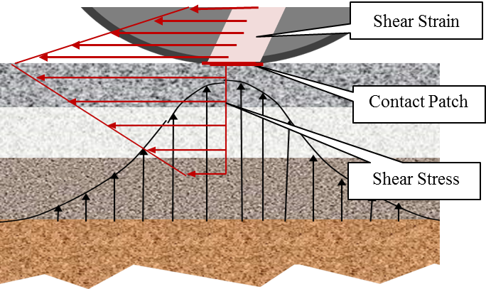
The phenomenon most often takes the
form of elastic deformation
measured in units of distance
(inches). The sketch below
illustrates shear strain
in the tire resulting from shear
pulse.
Whereas
the real value of
shear pulse is constrained (δ =
0),
the theoretical
value of shear pulseδ = 2Rθ -
S
can be used to
characterize the magnitude
of shear strain in the tire
-- hey, and δ = 2Rθ -
Scan
also be used to characterize
the shear stress in the
roadway pavement.
Exclamatory punctuation may
be appropriate.
In strength
of materials work, one
generally treats stress
as an independent variable, an
empirical consequence of an applied
force.
Meanwhile strain
is a measurable deformation
resulting from applied stress.
Here a conceptual reversal is
needed: Given a geometrically
derived strain (δ
≠
0),
what stress is being caused in the
tire-tread? Then too, what
force can be estimated as acting on
the pavement for each drive wheel?
That force can then be
compared with, say, tractive
effort.
It is beyond the scope of the Unsprung Secrets
puzzle to accomplish all that.
One might expect that even a small shear
pulse deformation of a truck
tire comprising rubber and steel belts
might require significant
circumferential forces, which then add
and subtract from pavement shear
stresses attributable to tractive
effort.
Do shear
pulses that damage roadways
offer any benefits to the
trucking industry?
Transient
State vs Steady State
Lingering
thus Lengthening Shear
Pulse
During the
transition
from a flat
roadway to an
upwardly
curved
profile, 2Rθ -
S≠
0, and the
tandem drive-axles
on a C-rig
impose a shear
pulseδ ≠
0
in the roadway pavement. The shear
pulse phenomenon arises in a Transient State
Zone along the roadway, wherein the
value of R
is changing. Moreover, the
magnitude of δ ≠
0
lingers into a Steady
State Zone, wherein R
is held constant, as illustrated
in this sketch...
In
a roadway hump, we see spatial
forces of compression
('squeezing') in the pavement
between the contact patches,
increasing in the "Transient
Zone"
on the left and then decreasing
in the "Transient Zone"
('stretching') on the
right.
The
C-rig-specific
phenomenon will have the same
magnitude for a roadway
dip. Here's irony for
you: The pavement would be
experiencing spatial forces in
compression between the
contact patches -- same as for
a hump. Go figure.
During
the "Steady State Zone" of
that particular roadway
hump, both drive-axles,
which are unsprung features
of the drive train, are
moving vertically along a
constant radius of curvature
R,
first concave upward then inflecting
to concave downward, all the while the
pavement suffers constant longitudinal
forces in compression from the C-rig's
shear pulseδ.
Think of drive-wheel tires
on a C-rig
as having 'analog memory', capable of
storing the value of a shear pulse
in one sense (squeezing) until it is
'erased' by a shear pulse in the
opposite sense (stretching).
The technical term is elastic
hysteresis. Thus the most
pronounced adverse effects attributable
to shear
pulse may
be the
accumulation
of heat
in the treads on drive-wheels, raising
temperatures, and increasing wear -- all
with no benefit for the
transportation of the truck's payload.
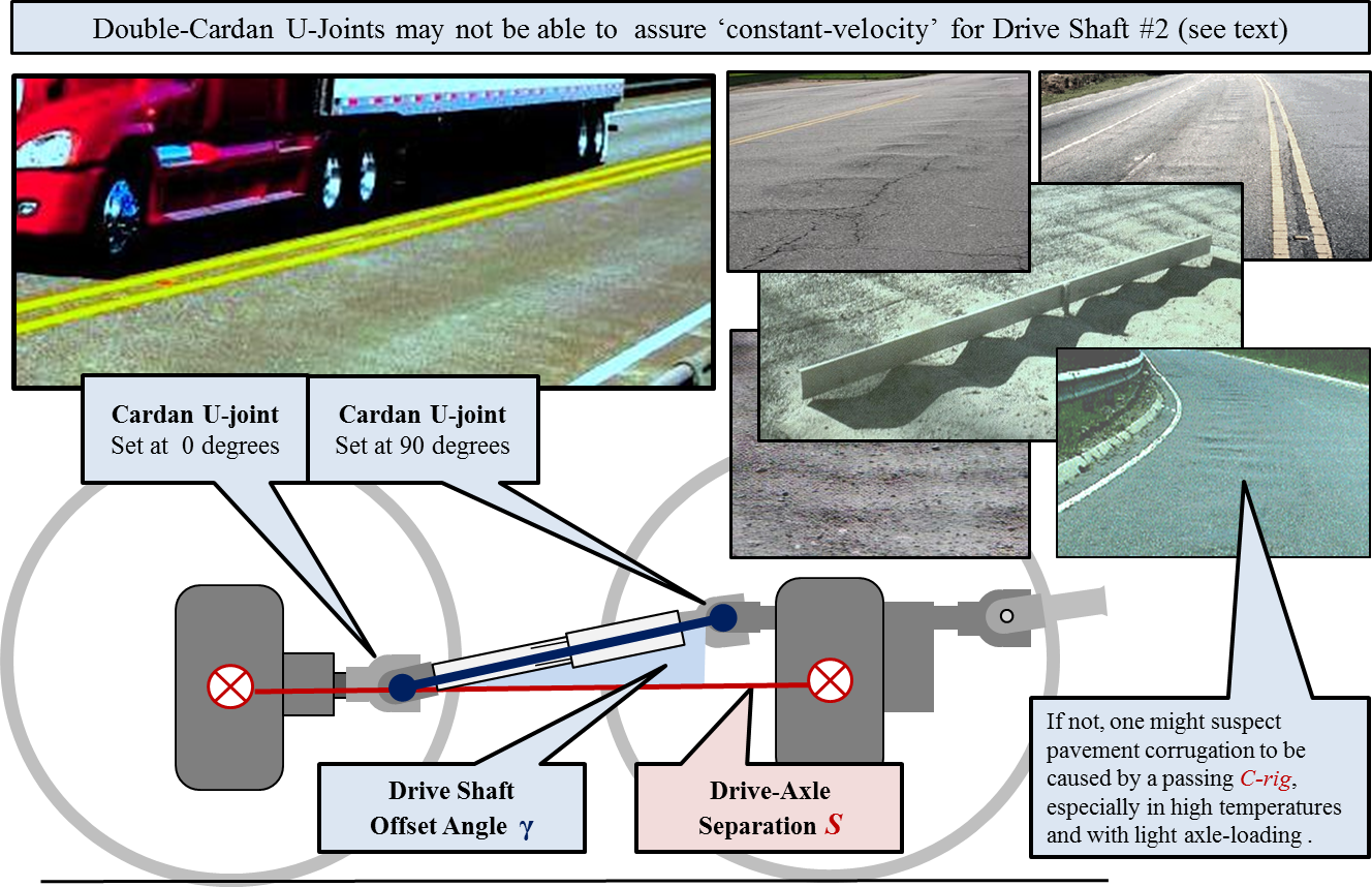
Pavement
Corrugation
Hot Pavements and
Unloaded C-rigs
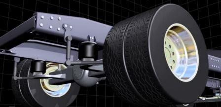
The photograph
of a magnificent C-rig
which was selected for illustrating the
Unsprung Secrets
puzzle, has been excerpted below.
It is being used here to draw attention
to pavement defects in the near lane,
which are variously called
'corrugation', 'rippling', or
'wash-boarding' by roadway
authorities. An image search on
the web turns up many such cases on U.S.
roadways.
The condition may be
common worldwide, although
photographic evidence is not
especially abundant. Here in
Brittany your puzzle-master has not
observed corrugation, even on unpaved
roads in the countryside.
In studying Drive Shaft #2 we came
across the Double
Cardan Shaft, which is sketched
below. The objective is to achieve
'constant velocity' (CV) for the shaft
-- more specifically to get rid of
sinusoidal variations in the angular
turning rates caused by Cardan U-joints.
Experts know that
successful CV depends on mechanically
managing the planes of rotation for
various values of the Drive Shaft
Offset Angle
γ. Given
that Drive Shaft #2 is rotating at
three times the axle turning rate
and that a truck wheel is
typically 42 inches in diameter,
one can calculate that spatial
waves caused by Drive Shaft #2
would be inflicted by the tandem
drive configuration at 42
π / 3 = 44 inches/wave
(or sub-multiples 22 or 11
inches/wave).
Proposed
Solution for the Unsprung
Secrets Puzzle
Confirm
the Explanation and Fix the Cause --
in That Order
In the absence of empirical evidence
to support the various hypotheses set
forth above, let us offer the solution
to the Unsprung
Secrets puzzle in the form of
a proposed explanation...
C-rigs
cause more damage to roadways
than B-rigs
because of one design
feature...
tandem
drive-axles.
Solvers are
invited to provide comments on this
proposal here.