 |
|
Copyright ©2015 by Paul Niquette. All rights reserved. |
|
| Solvers
of the Five Axles puzzle
discovered that differences in static axle-loadings
for two types of trucks, C-rig
and B-rig, cannot
explain differences in
roadway damage...
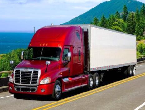
In either California or Brittany a freshly paved roadway may be considered 'perfect' with only gradual changes in elevation over long stretches. As vehicles of various kinds come rolling along, dynamic forces are imposed on the roadway pavement by their wheels. A typical segment of flat and level pavement is called upon to support the rather sudden application of wheel loadings: 950 lbs per wheel for a typical automobile, 4,444 lbs per wheel for a fully loaded C-rig and 6,666 lbs per wheel for a B-rig. After a period of time (some 9 milliseconds at 60 mph), weight is just as suddenly relieved on that segment and moved on to another. At a given location, such impacts take place five times for each C-rig or B-rig that rolls over it. Solvers may want to review how wheel-load, which is a vertical force, creates stress in the roadway materials underneath and necessarily results in strain. Two types of stress are especially important: compression and shear. There are a half-dozen conventional failure theories, including stress (normal or shear), energy (strain or distortion), fracture or creep.A roadway may start out in a 'perfect' condition when freshly paved but won't usually stay perfect. For the Unsprung Secrets puzzle we will set aside environmental causes, especially water erosion of the subbase and icing conditions that can crack pavements. Both may actually be more problematic in Brittany than in California. Roadways naturally do start out with gentle humps and dips. With wear and tear these can become imperfections in many forms. Our efforts must find out why damages are caused by C-rigs more than by B-rigs. Our suspicion lies where the rubber meets to road... Since the earliest horse-drawn carriages, vehicles have been sprung -- 'spring-loaded' to protect their contents from bumps and potholes. The vehicle's 'suspension system', which includes the heels and associated hardware, necessarily follow the vertical profiles of roadways. Those parts of the suspension system are said to be unsprung, and minimizing unsprung mass is an important subject in assuring road-ability of vehicles in the presence of various imperfections. Modern suspension systems assure safe-handling by drivers and comfortable riding for passengers. An ideal unsprung mass of zero would completely conceal vertical accelerations caused by irregularities in the roadway from the body of the vehicle and from people inside and from cargo in a truck. That ideal would not impose dynamic forces on the roadway apart from the varying static loads described above. A real suspension system on either a C-rig or a B-rig must accommodate non-zero unsprung mass. Thus the suspension system transmits inertial stresses onto roadways, potentially creating and then aggravating defects in pavements, making small cracks larger and shallow pot-holes deeper.  Trucking
regulations
limit static
axle-loadings
but do not
explicitly
limit dynamic
forces
attributable
to unsprung
mass.
Let us explore
that subject
as it pertains
to roadway damage. Trucking
regulations
limit static
axle-loadings
but do not
explicitly
limit dynamic
forces
attributable
to unsprung
mass.
Let us explore
that subject
as it pertains
to roadway damage.Here is a convenient model for a truck wheel and prorated mechanical elements in the suspension system. Using the sketch below, we find that mU = wU / g slugs, where wU is the unsprung static weight in pounds and g is the acceleration of gravity (32.2 fpsps). 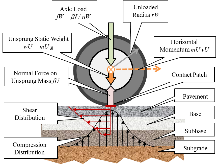 Legend for Unsprung Secrets Model.
The weight wU and therefore the mass mU for a given wheel and its associated hardware varies with the rôle being performed: [1] steering, [2] propelling, and [3] supporting the truck -- as can be identified in this sketch from the Five Axles puzzle... 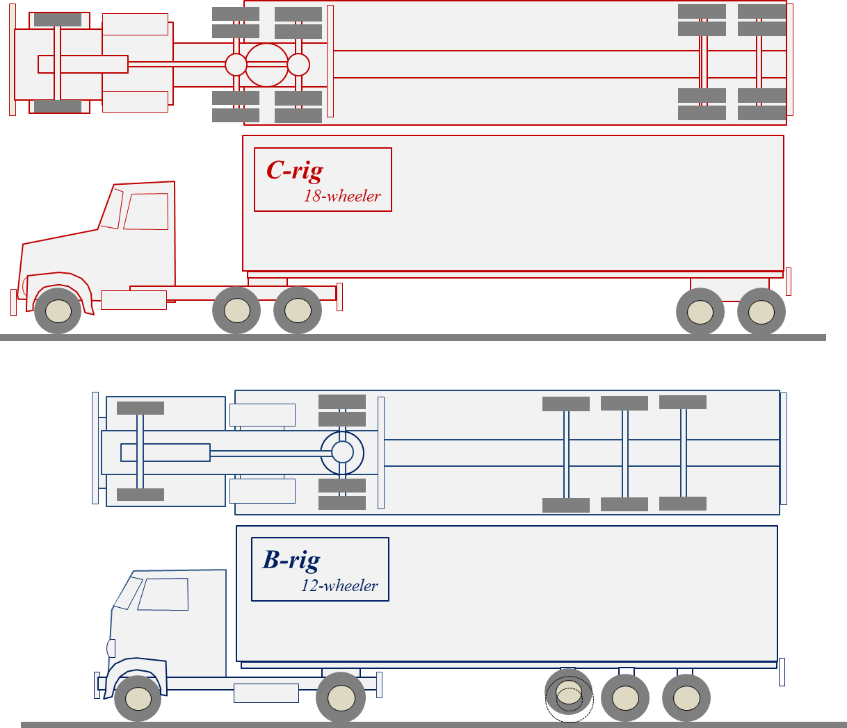 Typical parameters from product literature for truck-tires will be used for modeling dynamic impacts on roadways: tire diameter 42 inches and weight 130 pounds. The unsprung static weight wU -- tire, rim, hub -- totals about 260 pounds, thus the unsprung mass mU ≈ 8 slugs. If roadway damage by trucks is to be blamed on onerous pounding by unsprung mass, one might reasonably suppose that vertical acceleration afforded by potential energy would apply. Solvers of the Five Axles puzzle will notice that unsprung static weight wU of 260 pounds (lbs) is quite small compared to the static wheel-load fW pressing downward by the spring or, most commonly these days, from air-filled bellows in the suspension system... C-rig: fW = (wT + wL) / nW - uW ≈ 80,000 / 18 - 260 = 4,444 - 260 = 4,184 lbsThe ratio fW / uW represents the acceleration aY of the unsprung mass if it were free to move vertically compared to the acceleration of a body falling under the influence of gravity alone, which is g = 32.2 fpsps. In solving the Unsprung Secrets puzzle, we need to show that the five wheel-impacts on a given roadway segment are cumulatively 1.5 times worse for the C-rig compared to the B-rig. However, the ratios of acceleration are the wrong way 'round for making that case: aY = 16.1 g for the C-rig and aY = 24.6 g for the B-rig. So much for potential energy in the impact comparison. The tractive effort of the prime mover in the tractor provides kinetic energy to the truck as a whole, including the unsprung mass. We continue our analysis by postulating that the dynamic impact of the unsprung mass of a truck wheel is somehow proportional to that kinetic energy, some part of which gets to the roadway pavement. Each truck-wheel has translational kinetic energy given by mU vX 2 / 2 ft-lb. Sophisticated solvers will want to take into account the fact that the wheel is also rotating at some angular velocity ωU radians-per-second, which is given by ωU = vX / rU, where rU is the radius of the wheel in feet. The rotational kinetic energy is given by iU ωU 2 / 2 ft-lb, where iU is taken as the moment of inertia for a cylinder of radius rU and given by iU = mU rU 2 / 2 lb-ft/sec2. The total kinetic energy of the wheel is the sum of its translational and rotational kinetic energies... mU vX 2/2 + iU ωU 2/2 = [mU vX 2 + (mU rU 2/2) ( vX / rU) 2] / 2 = 3 mU vX 2 / 4A wheel with mass mU moves along the roadway at the same rectilinear velocity as the truck vX feet-per-second. Consider what occurs at the instant the unsprung wheel passes over a deflection in the roadway -- even a mild deflection. From the diagram above, we see that, whereas 16 of the 18 wheels on the C-rig are configured as duals, only 4 of the 12 wheels on the B-rig are configured as duals. Should solvers consider this to be one of the Unsprung Secrets? Not so much. Here's why... The kinetic energy of the unsprung mass is proportional to the mass mU. The combined mass for dual wheels will be twice that of a single wheel 2mU. By the same token, however, the two contact patches in the dual configuration can be presumed to transfer energy equally and thus nullify differences in roadway impacts attributable to kinetic energy from a wheel configuration with doubling the mass. The
kinetic energy of a 260-lb
truck wheel at 30 mph is
about 11,600
ft-lbs.
At twice that
speed, 60 mph,
that figure
quadruples to
46,500 ft-lbs.
Oh, but kinetic
energy is
really a horizontal
kind of
thing. What percentage of kinetic energy will get transferred to the roadway pavement?Kinetic energy is a scalar quantity not a vector. Nevertheless, to answer the question, we can avoid vector-mathematics (force, momentum, impulse), and we can also set aside local variations in tire pressure, mechanical distortions of contact patches, and flexing of sidewalls. Here's how: We simply observe that in rolling over a deflection -- either a hump or a dip -- the wheel must follow a longer path than it would in continuing on the level roadway. Here is a sketch of a roadway deflection. It is exaggerated in the vertical direction. One might expect a new roadway to have gentle deflections of no more than a few inches over a span of several feet. Please excuse a statement of the obvious... 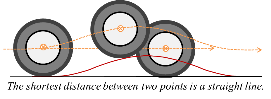
A small deflection amounting to a 1-ft hump over a 100-foot span of the roadway will result in a change of kinetic energy by about 0.5%. A 260-lb truck-wheel at 60 mph might then transfer 0.5% of its kinetic energy or 232 ft-lb to the pavement over the span of the hump. That's not an much of an impact, but -- hey, whatever it amounts to, we do not see any difference between the C-rig and B-rig in the transfer of kinetic energy via unsprung wheels. By the way, the model transfers kinetic energy to the roadway not as a vertical impact but as a horizontal shear force along the pavement. Hmm... A truck's suspension system protects the roadway from damage by the truck as much as it protects the truck itself from an already damaged roadway. For our solution to the Unsprung Secrets puzzle, we must look for a significant difference in the designs of the C-rig and the B-rig. Our investigation of kinetic energy has given us a clue...
|
|||||||||||||||||||||||||||||||||||||||||||||||||||||||||||||||||||||||||