|
Version 2.0 Copyright ©2021 by Paul Niquette. All rights reserved. |
|||||
| To the
question posed by the Pocket
Rocket puzzle, "Does
the NIP concept work?" the answer is...
The Niquette Inertial Propulsion (NIP) concept does not work because Inertial Propulsion, also known as "reactionless drive," cannot work. For that, blame Newton's Laws of Motion. Countless inventors have tried in vain to develop self-contained drive systems that do not require physical interaction with their surroundings. In space, of course, there is nothing for a drive system to interact with. Accordingly, 'rocket science' is really about burning up fuel, which is most of the mass carried aloft by every spacecraft, and spewing the exhaust overboard at high speed. Satellites need small chemical thrusters for orbital adjustments. Just imagine the immense monetary value of devices that produce propulsion in space -- endlessly powered by the sun!Inertial Propulsion (IP), therefore, has become something of a Holy Grail for inventors. Unfortunately, for the outcomes so far, the phrase "wholly fail" seems more appropriate. With eyes on the prize, though, inventors keep trying: publishing webpages, posting work-in-process pictures -- even making progress reports by video. On page 25 of his 1980 memoir, Death of Rocketry, Robert Cook features a sidebar in which he comes right out and says, "Newton's laws of motion are not totally correct," which seems to be a sentiment shared and often expressed by inventors of IP devices. 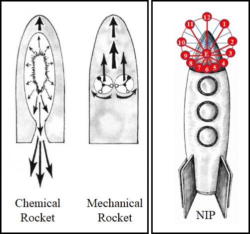 Fig. 2 Schematic
Sketch of CIP and NIP Providing Launch Thrust
Cook's e-book also includes a sketch of CIP performing all-up rocket-launching duties. In Fig. 2, alongside CIP, we see NIP depicted in the same ambitious application. Sure hard to imagine how either could deliver that much power from photovoltaic cells and batteries. In the Pocket Rocket puzzle, however, NIP was proposed as an alternative for small 'puffer' rockets. Niquette Inertial Propulsion may not be the "most elegant IP invention," but it was cooked up in 2021 to be the best invention for proving why Inertial Propulsion cannot work. Confusion and Controversy Sophisticated solvers are invited to provide links to published exceptions.References tend to be rather timid, saying things like, "The expression centrifugal force is the subject of confusion -- even occasional controversy." We will use NIP to clear up the 'confusion'. Then maybe there won't be 'controversy' any more. Using our analysis of the NIP concept, sophisticated solvers will see why any confined IP concept that uses internal rotating masses will fail to produce a linear external force. Moreover, that conclusion must apply to all IP inventions, regardless of how masses inside are repetitively moved! Newton's First Law It would sure be hard to say anything more elementary than, "An object at rest will stay at rest, and an object in motion will stay in motion unless acted on by a net external force." The mass M inside the NIP device is definitely "an object in (repetitive) motion" thanks to the motor-driven, telescopic arm to which it is attached. The mass M would "stay in motion" in a straignt line were it not for the track by which its motion is constrained into a circle. The track exerts a "net force" upon the mass -- not vice versa! Fig. 3 shows that. 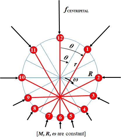 Fig. 3.
Simplified NIP Showing Mass M
Rotating Clockwise.
Fig 3 shows the real force fCENTRIPETAL acting toward the center of the circular track. That is the exact opposite of the fictional force fCENTRIFUGAL which is depicted in the Pocket Rocket puzzle Fig 1. as radiating outward from the rotating mass M. Solvers may find it helpful to think of the moving mass M as being 'pulled' rather than 'pushed' toward the center by the circular track. Either way, Newton's Third Law says, "To every action there is always an equal and opposite reaction." Best not to think of the centrifugal force in Fig. 1 as the "equal and opposite reaction" to the centripetal force in Fig. 3. Here's why: The two forces would simply cancel each other out, and mass M would not be coerced into circular motion. Bummer. Oh,
but that would only be the case if
both forces (centrifugal force
and centripetal
force)
were real. Since centrifugal
force in Fig.1 is not
real, what does provide the "equal
and opposite reaction" to the centripetal
force in Fig 3.? Answer:
The rigid structure of the NIP device,
which is pulling the circular track inward
toward the center of rotation!
So much for centrifugal force. But wait. Centripetal force is but one of three kinds of forces acting on Mass M (in space, of course, a fourth force, weight, is zero). The other two are inertial forces and frictional forces. Both are real, so let's get to work on them. Inertial Forces In Fig.4, the black arrows do not represent forces. Instead they indicate the instantaneous velocity v of mass M as it passes each of the equally-timed positions on the NIP guide track. 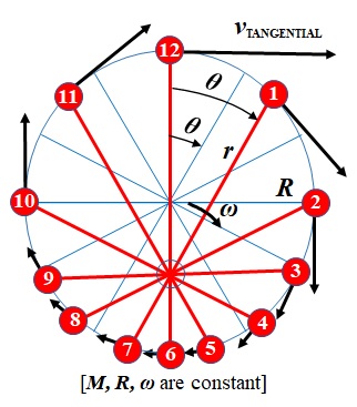 Fig. 4.
Simplified NIP Showing Tangenial Velocity v
of Mass M.
As described in NIP Theory of Operations, at position 12, v is at its highest level. Later, at position 6, v is at its lowest level. By Newton's Second Law (f = M a), decreases/increases in velocity demand deceleration/acceleration of mass M. That's "inertia," people.
Meanwhile, the synchronized
counter-rotating mass M (not
shown in Fig. 4) passes its corresponding
positions: accelerating (through 5, 4,
3, 2, 1) and decelerating (through 11, 10, 9, 8, 7). One
readily sees that while the clockwise rotating
M demands clockwise 'braking'
torque, the counter-clockwise rotating M
is delivering (by inertia) counter-clockwise
'cranking' torque, which satisfies that demand
through the drive gearing. And vice
versa. So much for inertial forces,
which simply cancel each other out within
the Pocket Rocket.
Frictional Forces Whatever the design of its surfaces and bearings, the guide track imposes a normal force against mass M, which varies with the instantaneous arm length r. That produces a variable frictional force opposing velocity v and thus demands matching variable torque from the drive motor. Meanwhile, see Linear Linkage for an idea that might replace sliding friction in the telescoping NIP arms with a low-friction, hinged concept. All torques match each other and are contained within the Pocket Rocket, making frictional forces irrelevant to the question set forth above. Sophisticated solvers might notice that, with inertial forces canceling each other out, the only torque required from the motor is frictional. Niquette Inertial Propulsion Device Given the conclusions reached on this page we must observe that... Even if the NIP concept complies with all of its design criteria, it will not work.There is no reason to proceed with the design of an NIP device. Heck, if the NIP concept does not work based on Newton's Laws of Motion, it makes no sense to carry out an actual design. Inventors of IP devices sure do that, though. They go on to build and to tinker with their IP contraptions. As we have seen, they file for patents, too -- unabashedly disclosing to the world all the details of their IP inventions, hoping to profit from huge royalties. It is fair to wonder, however, whether the NIP concept has any hope of functioning. In other words, would it even be possible for an IP device to comply with all nine criteria? If not, then NIP is hardly qualified to exemplify the fool's errand that inventors of IP devices have taken for themselves. Eight of the nine criteria are straight forward enough -- if not trivial to implement. However, criterion number four really requires some inventive effort... Coaxial and Coplanar Configuration Coaxial drives for the counter-rotating arms can be fulfilled by gearing arrangements already in service. Coplanar drives can be readily accommodated. Indeed they are featured in several IP designs (see Fig. 2). Putting both requirements together, though, puts the feasibility of any NIP design in doubt. So, why include criterion number four? One word answer: Shimmy.Counter rotation requires that each mass must have its own track. Duh.
 Fig. 5
NIP Device
Designed for Synchronized Coplanar
Counter-Rotating Masses Here is a big 'if': If pulsating thrust
forces from masses in eccentric rotation could
actually 'escape' the NIP device
(unfortunately that's forbidden by Newton's
Laws of Motion), the simultaneous
pulses of force would be applied separately to
the structure of the spacecraft. For example, one of the two NIP masses might be lined up with its 6-to-12 thrust line pointing directly at the spacecraft's contemporaneous center of mass (zero moment arm). The other thrust line would be offset to one side. Left uncorrected, the resulting torque would cause the whole danged spacecraft to rotate at a steadily increasing angular velocity!A star-tracker in the spacecraft would need to detect such unwanted rotations and to have the authority to command speed corrections by means of an auxiliary NIP device to restore angular orientations and stop all spacecraft rotations. The spacecraft would thus be caused to shimmy, which is an unwelcome result for sensitive on-board instruments and people. Invention
for Criterion Number Four 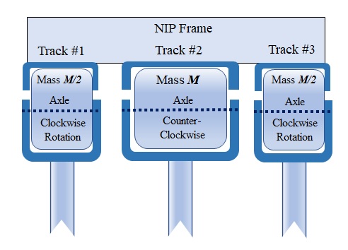 Fig. 6. Invention for Compliance with Criterion Number Four Here is a
schematic sketch showing an edge-on
cross-sectional view of all three masses passing
each other at the 12 o'clock position. Each
mass is depicted as a cylinder rolling in its
track with its axis affixed to a stirrup at the
end of its telescopic arm. Thus, each mass
is augmented by its angular moment of (rolling)
inertia without adding launch-weight to the NIP
device. Kind of neat, huh? Too bad the
NIP concept won't work.
What about "working" models? Inventors of IP devices sure do build "working" models -- often calling them "prototypes," as if they are about to release manufacturing drawings to a factory. For space applications, though, simulation of weightless environments are not widely available. Also, without vacuum chambers in workshops, demonstrations of IP devices are vulnerable to mischief by windage from spinning masses, so IP devices designed for space are difficult to demonstrate. One enthusiast, Ivan A. Loukanov, exults that "a new version of Tolchin inertial drive redesigned and built by a research team at Moscow Space Research Institute was installed and tested on board a Jubilee satellite in 2008. Results revealed that the drive is promising and can be used to correct the orbit of satellites without ejecting any propellant mass into space." That ought to have made headlines in the popular press over the past 13 years, one thinks.One simple demonstration calls for hanging an IP device from the ceiling like a pendulum, turning it on, and measuring the deflection from straight down. The two counter-rotating masses (cw AND ccw) may cancel each other out in the torque department, but the drive motor has to chose its own spinning direction from one or the other (cw OR ccw). That brings a torque unbalance to the demonstration, which must be matched by the deflected weight of the ensemble. Hey, the spacecraft would wind up rotating the opposite way! The most common demonstrations simply put the IP device on wheels. One typical video gives a mighty fine clue for why the IP device jerks along forward on a level flat surface. The fallacy has a name, "slip stick" (not to be confused with slipstick). The thing is quite obviously interacting with the platform on which it stands. That's a gotcha. Indeed, that IP device is merely exploiting the fact that stiction is generally stronger than friction. Standing by to receive comments, especially from inventors of inertial propulsion devices...
|