|
Draft 3.2 by Paul Niquette June 19, 2002 Internet version published December 31, 2007 Copyright ©2007 Paul Niquette. All rights reserved. Updated June 27, 2009 Possibly the most subtle problem
in automatic train control, loss-of-shunt, seems to defy First Principles,
raising the question...
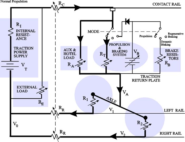
The exploration here of current-hogging applies simplified, non-numeric thought experiments. Four cases are modeled as Thevinen-equivalent circuits, with linear configurations assumed to be conditionally selected for each operating mode of the train. In the figure on the right, RR represents the two Running Rails as series resistors, gang-variable with distance from Negative Return V0. Reality, of course, would include variable inductances attributable to properties of iron and, for transients, stray capacitance significant to the model. As presumed under the hypothesis of the model, two wheel-rail resistances R1 and R2 are depicted as separately variable and thus subject to unbalance in conductivity at their respective contact patches. Traction Power Supply voltage VT is modeled as a battery with Internal Resistance RI. In reality, the source is typically a delta-wye driven rectifier bank with substantial ripple. During reversals in rail current between propulsion and braking, that ripple affords multiple opportunities for unbalances in wetting current. The voltage at the Traction Return Plate VA represents resistive compliance afforded by R1 and R2 and thus VA is distinguished from V1 and V2. The Normal Propulsion Case supports two simultaneous current paths through the vehicle from the Contact Rail to the Running Rails. The Traction Power load is represented by RT. Auxiliary & Hotel Load are modeled as RA. When the train is in motion, RT << RA. Both paths are subject to the common potential VA imposed at the Traction Return Plate. It is important for the hypothesis being postulated here to note that during Normal Propulsion, the voltage at the Traction Return Plate VA will be positive with respect to V1 and V2.
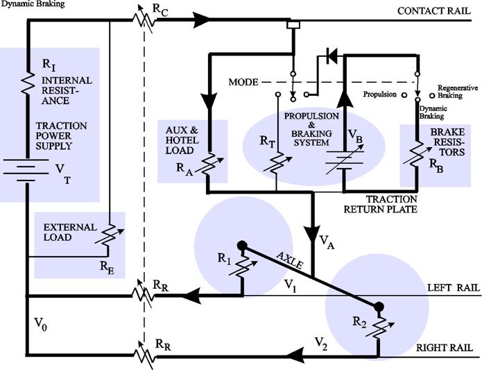
During Dynamic Braking, the Auxiliary & Hotel Power loads continue to draw power via RA from the contact rail, which maintains wetting current presumably in both Wheel-to-Rail contact patches. Traction Power Load RT is depicted in the sketch on the right as being disconnected from the contact rail. Dynamic Braking results from the traction motors acting as generators, producing VB, which is shown here independently dissipating kinetic energy from the vehicle in Braking Resistors RB on board the vehicle. Note again, the voltage at the Traction Return Plate VA, which is now totally attributable to the Auxiliary & Hotel load RA continues to be positive with respect to V1 and V2.
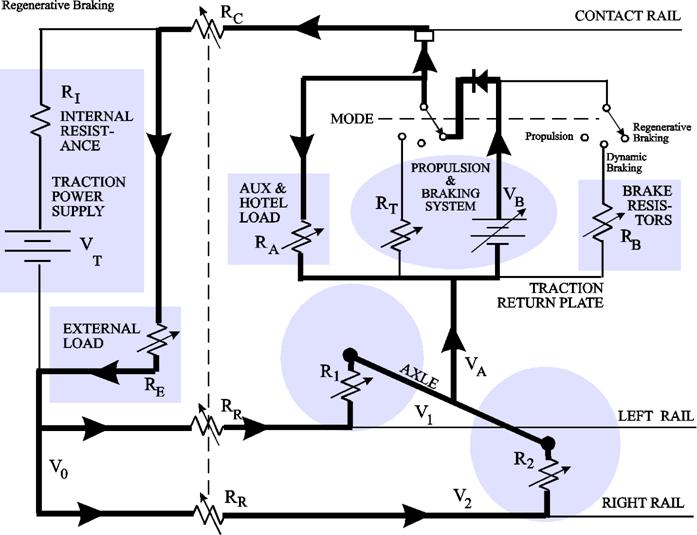
For Regenerative Braking to be operative, another train must be present in the nearby trackway, imposing an External Load RE on the Traction Power Supply voltage VT. As shown in the sketch, RE forms a voltage divider with Internal Resistance RI of the Traction Power Supply, lowering the Contact Rail voltage thereby making the contact rail "receptive." Traction Motors acting as generators energized by the vehicle's motion produce a Dynamic Braking voltage VB. Voltage VB is shown connected through a diode to the Contact Rail supplying current to the nearby External Load RE. The diode in the sketch symbolizes assurance of receptivity of the Contact Rail. The Braking Resistors RB inside the vehicle will necessarily be disconnected from both the Contact Rail and from the Propulsion and Braking System. Auxiliary & Hotel loads draw power via RA -- but from inside the vehicle not from the Contact Rail. Contrary to popular belief, Auxiliary & Hotel Power cannot be counted on to assure uninterrupted wetting current through Wheel-to-Rail contact patches. Indeed, it should be noted that the wheel-rail current actually reverses, and voltage at the Traction Return Plate VA will be negative with respect to V1 and V2 during Regenerative Braking. Thus, the Wheel/Rail current must pass through zero when transitioning from either Normal Propulsion or Dynamic Braking to Regenerative Braking. That reversal in polarity gives rise to the...
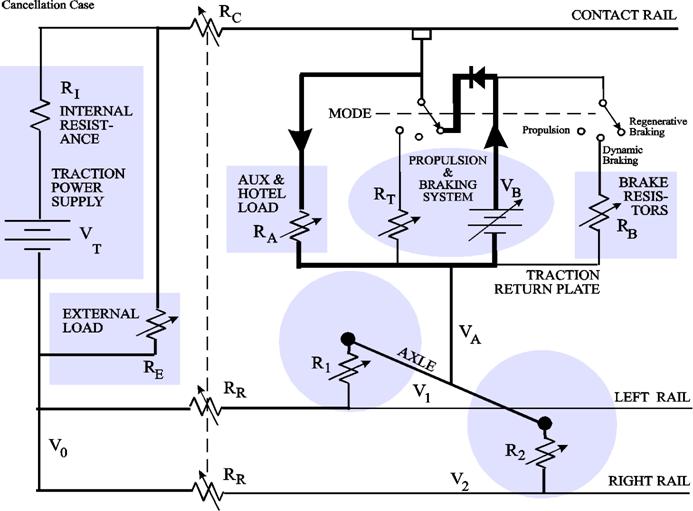
The voltage produced by Dynamic Braking VB is called upon to supply power for only Auxiliary & Hotel loads RA during some finite interval of deceleration for a vehicle configured for Regenerative Braking. During that interval, R1 and R2 are deprived of wetting current and may become indefinitely large such that VA would in theory be allowed to float upward toward the local Contact Rail voltage (less VB). At some value of VA, however, one of the contact patches will surely break through its respective contaminating film (contact oxidation), possibly influenced by another train in the same trackway that may independently be imposing unequal values for V1 and V2.
What happens in each Wheel-to-Rail interface at the instant a vehicle emerges from the Cancellation Case? If the answer is that Wheel-to-Rail contacts always develop wetting current equally, thereby assuring simultaneous connection, then a current-hogging hypothesis would not be supported, and the thought experiment can end right here.  On the other hand, as the voltage at the Traction Return Plate VA gradually rises above zero, the contact patch on one of the rails the left, say might emerge with a slightly higher propensity to break through the contaminating film (contact oxidation) on the left rail. If so, one might reasonably suppose that R1 would enter into its metal-to-metal conductivity first and take on a lower resistive value than R2. Current flowing through R1 would drop the voltage at the Traction Return Plate VA thereby reducing whatever propensity for breaking through contact oxidation enjoyed by the patch on the right rail. The unbalance would become exaggerated such that the right rail might not get connected for some significant interval of time, while stray capacitances are being charged. Thus, the expression "current hogging." Loss-of-shunt is a safety concern for automatic train control systems, which depend on shunting for train detection. As shown above, a train under Regenerative Braking must necessarily pass through the Cancellation Case, during which wetting current vanishes and loss-of-shunt may result. Current hogging has the potential to extend the duration of that loss-of-shunt thereby allowing the train control system to take inappropriate actions. Bay Area Rapid Transit (BART) operates an automatic train control system equipped with a "Sequential Occupancy Release System" (SORS). The purpose of SORS is to assure protection of the rear-most vehicle in a consist from "following move" collisions. Shunting of the running rails asserts "raw occupancy" in successive train control track blocks as the train moves along the trackway. SORS manages an elegant "check-in/check-out" algorithm. The occupancy of each block is "latched" in the train control system and will not be "released" until the lead vehicle is detected in a block farther along the trackway than the length of the train. Loss-of-shunt in the lead vehicle of sufficient duration will prevent release by SORS of a latched occupancy beyond the end of the train, leaving behind a stranded queue. Stranded queues are relatively common -- and unexplained -- but not unsafe. Stranded queues are treated by the train control system as "false occupancies" and thus they impact only service availability. A train control supervisor must authorize the resetting of a stranded queue after assuring that the occupancy is indeed false. Every stranded queue does act as an "event" captured in the SORS memory, faithfully recording occurences of loss-of-shunt. Unexplained stranded queues inspired the study published here.
Update The fatal 2009 Washington Metro train collision was a "following move" disaster. Unlike BART, Washington Metropolitan Area Transit Authority (WMATA) operates an automatic train control system that is not equipped with a "Sequential Occupancy Release System" (SORS). Applying concepts and terminology developed in the study above, let us consider the following scenario:
Supplementary Draft 1.0 August 16, 2009 by Paul Niquette Copyright ©2009 Paul Niquette. All rights reserved.
Returning to the Dynamic Braking case, we observe that the Contact Rail is effectively disconnected from the Propulsion & Braking System as depicted in the sketch above. This is a coordinated mode for all vehicles in the consist. The electrical conditions thus established can be sustained for many seconds, during which the wheels of a given vehicle might well be postulated to roll completely through a given track block or problematically through more than one track block. Accordingly, during Dynamic Braking the electrical properties of the Auxiliary & Hotel Power Load will prevail. Traction power voltage is not suitable for used in its raw form. The Auxiliary Power Supply Equipment (APSE) in each vehicle first applies an electrical inverter to change the high voltage DC to AC thence to deliver power via transformers at appropriate voltage levels thoughout the vehicle. The fundamentals of a typical electrical inverter can be seen to switch current on and off rapidly at the front end creating pulsations at the chopping frequency (most likely 60 Hz). The pulsating current through wheel/rail patches repeatedly goes to zero every 81/3 milliseconds (or passes through zero, depending on characteristic impedances). With every pulse, wetting current vanishes and must be restored. In effect, these are rapid repetitions of what has been described in the main article above as the Cancelation Case, to which the following Key Question pertains: What happens in each Wheel-to-Rail interface at the instant a vehicle emerges from the Cancellation Case (zero-current)? If the answer is that Wheel-to-Rail contacts always develop wetting current equally, thereby assuring simultaneous connection, then a current-hogging hypothesis would not be supported.and to which another question needs to be addressed Let us assume that one wheel/rail patch has indeed engaged in current-hogging by breaking through its contaminating film (contact oxidation), establishing metal-to-metal conductivity and setting a voltage level at the Traction Return Plate that keeps the other rail from breaking through (see main article above). Does that rail then become more likely to do so again a few milliseconds later?In other words, does the rail or the wheel have a hysteretic memory? The rail does exist in a stray capacitance environment, as does the Traction Return Plate. Then too, perhaps relative temperatures of wheel treads may play a part in perpetuating a current hogging condition. Note too that the internal electrical
configuration of the Dynamic Braking case also exists for what might be
called the Stopped Train Case. The technical questions raised in
this supplement might best be addressed by empirical experiments with a
stationary vehicle or consist.
|