|
Copyright ©2011 by Paul Niquette. All rights reserved. |
|||||||||||||||||||||||||||||
  Solvers
of
the World's Fastest Train
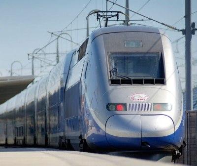
puzzle will recognize the photograph on the right as
that of the V150,
the Alstom
train that set a world record speed of 574.8 kph
(357.0 mph) on April 3, 2007, as recorded in this video.
That
the view is from the rear of the train can be confirmed
by the red lights and by the unoccupied cab. There is a
third clue: The pantograph
has been deployed. Whereas the V150 has a power
car at each end of the consist,
each with its own pantograph, the pantograph only at the
rear of the train is used to collect power from the overhead
system for distribution throughout the train. Solvers
of
the World's Fastest Train
puzzle will recognize the photograph on the right as
that of the V150,
the Alstom
train that set a world record speed of 574.8 kph
(357.0 mph) on April 3, 2007, as recorded in this video.
That
the view is from the rear of the train can be confirmed
by the red lights and by the unoccupied cab. There is a
third clue: The pantograph
has been deployed. Whereas the V150 has a power
car at each end of the consist,
each with its own pantograph, the pantograph only at the
rear of the train is used to collect power from the overhead
system for distribution throughout the train.
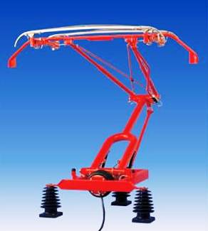
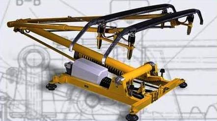
Pictured above are two examples of
modern pantograph design:
the Schunk
Model WBL
on the left and the Faiveley
Model EPDE
on the right. Both are designed for high speed
trains, featuring integrated pneumatic controls,
individual suspension of carbon collection strips,
vertical head guidance and fast lowering
devices.
 Most
people
will recognize these devices, for they apply the same pantograph design as those
simple spring-loaded assemblies atop modern light
rail trains placidly plying their streetcar
services on trackways embedded in the middle of city
boulevards. Most
people
will recognize these devices, for they apply the same pantograph design as those
simple spring-loaded assemblies atop modern light
rail trains placidly plying their streetcar
services on trackways embedded in the middle of city
boulevards.
Unchanged in concept for decades, the standard configuration is shown in Sketch 1 on the right, with its main components called out: stabilizing arm that keeps the pantograph head level and control arm that actively moves the head vertically to keep the force on the contact wire within a narrow range. In high-speed trains, the practice is to lock the lower arm in a fixed position, which reduces the inertial mass that has to be raised and lowered in real-time.
Meanwhile, automatic controls in the pantograph system must maintain the requisite contact force, adjusting rapidly for variations in the track, overhead wire, and swaying of the train as indicated in Sketch 2. Finally, under emergency conditions, the control system must be designed to drop the pantograph abruptly. Watch this clip for an example of what can go wrong.
Have a look at the picture of the Acela below, which is a view from the front of the train, and we can see the "knuckle" is facing backward, so that the contact strips are being pushed along the contact wire. The picture on the right shows a close-up of the pantograph. It shows something else, too... 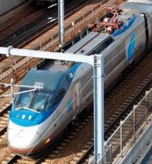 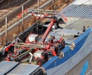 On Acela trains, each power car is equipped with two pantographs. They face in opposite directions. Unlike the V150, which distributes traction power to all cars in the consist from the rear pantograph, the Acela applies traction power only in the power car itself collected from overhead by one of its own pantographs -- always the pantograph selected for its "knuckle" facing the rear of the train. The
rationale
for the rear-facing "knuckle" will become clear to
solvers of the Pantograph Design
puzzle using a hypothetical train. Let the upper
arm on its pantograph be six feet in length. When
deployed at a nominal level, the pantograph reaches
upward from the 'knuckle" a distance of three feet to
the contact wire.
What are your estimates for the
following table entries:
|
 Overcoming wind resistance of the pantograph
would seem to be a minor challenge for any train
developing thousands of horsepower. Still, the
V150 deploys only the rear pantograph on each consist
and has roof fairings over the idle pantograph stowed
in front.
Overcoming wind resistance of the pantograph
would seem to be a minor challenge for any train
developing thousands of horsepower. Still, the
V150 deploys only the rear pantograph on each consist
and has roof fairings over the idle pantograph stowed
in front.  The frontal areas of the contact strips and
their holders are held perpendicular to the relative
wind and dominate the aerodynamic
The frontal areas of the contact strips and
their holders are held perpendicular to the relative
wind and dominate the aerodynamic